Simple Optical Tracking
DIY camera tracking of objects that are moving on the ground, with just a webcam and a few lines of code

The setup that will be covered here, allows you to track an object that moves on a specified plane (e.g. on even ground) using just one webcam and a few lines of Python code. The camera has to be in an elevated position, observing the plane and the object you want to track.

The foundation for the tracking algorithm is the pinhole camera model. This model allows you to get the real-world position \([\color{red}X_W, \color{green}Y_W, \color{#007FFF}Z_W\color{white}]^T\) of the \(\color{orange}\text{Object}\) you want to track using pixel data from the image. For this, you need to identify 3 things:
- The image coordinates \([\color{red}X_I, \color{green}Y_I\color{white}]^T\) of the object
- The intrinsic parameters of the camera
- The Rotation \(R_W^C\) and translation \(t_W^C\) from World Coordinates to Camera Coordinates:
\([\color{red}X_C, \color{green}Y_C, \color{#007FFF}Z_C\color{white}]^T = R_W^C \cdot [\color{red}X_W, \color{green}Y_W, \color{#007FFF}Z_W\color{white}]^T + t_W^C\)
Intrinsic Parameters
The first step of determining the image coordinates (the actual pixel positions of the object) can be done in various ways. You can use segmentation or object detection algorithms, for example. Choosing a suitable method here depends on the situation and is out of the scope of this post. For simplicity's sake, let's just assume that the image coordinates are known already.
This brings us to the next step, the intrinsic parameters of the camera. In a perfect world, The camera we use behaves like a pinhole camera. In such a scenario, you could just draw a light ray from each pixel in the image, through the pinhole, pointing exactly to the corresponding object in the real world
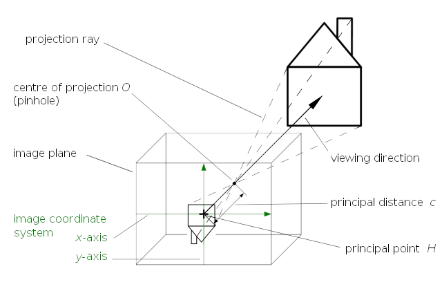
This means, that the image coordinates are connected directly to the real-world object by the projection rays. The origin of the camera coordinate system is the center of the projection \(O\) (aka. the pinhole). Computing the 3D reconstruction from image coordinates is like following those rays from the known pixel position, through the pinhole until you reach the object. Understanding the geometry behind this is easier if we first follow that ray in the opposite direction (from known world coordinates to the pixel positions) and then turn that process upside down. Let's say, the world coordinates are known and transformed into the camera coordinate system. To make everything easier, those transformed coordinates are also scaled down so that they are exactly one unit away from the center of the projection.
- \(\hat{X}_C = \frac{X_C}{Z_C}\)
- \(\hat{Y}_C = \frac{Y_C}{Z_C}\)
- \(\hat{Z}_C = \frac{Z_C}{Z_C} = 1\)
These scaled-down coordinates (emphasized by the \(\hat{\sqcup}\) symbol) can be projected onto the pixel coordinate system using the principal point \([c_x, c_y]\) and the focal length \([f_x, f_y]\). For this, the parameters are placed inside the camera matrix \(K\) that projects the normalized coordinates \([\hat{X}_C, \hat{Y}_C, 1]^T\) onto the image plane to get the actual pixel positions.
- \( K = \begin{bmatrix} f_x & 0 & c_x \\ 0 & f_y & c_y \\ 0 & 0 & 1 \end{bmatrix} \)
- \([X_I, Y_I, 1]^T = K \cdot [\hat{X}_C, \hat{Y}_C, 1]^T\)
All the equations above assume that the camera in use follows the pinhole camera model. However, this model is idealized and doesn't quite represent reality. In reality, camera lenses are used instead of a pinhole. Those lenses are essentially doing the same thing but add some additional distortions to the image so that the pixel/image coordinates aren't quite at the same place as they would be with a pinhole.
Determining the lens distortion parameters as well as the camera matrix can be done with openly accessible libraries like opencv, or with tools like the Matlab Camera Calibrator. The details of that process can be found on those sites and aren't discussed here for that reason.
Rotation and Translation from World to Camera-Coordinates
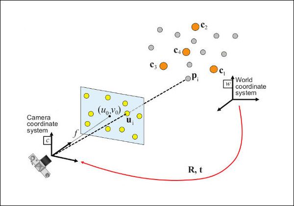
The third thing you need to determine for the 3D reconstruction is the relation between the camera- and the world coordinates. It is expressed using the rotation \(R_W^C\) and the translation \(t_W^C\). These parameters are also called extrinsic parameters and can be determined using a perspective-n-point transformation. The transformation requires at least 4 markers that are placed on the plane, you want to observe with the camera. The markers cannot be colinear and you have to know their exact position in world coordinates. Once you have placed the markers and know their exact locations, you can take a picture with your camera and determine the corresponding points in image coordinates
Let's say we have the following corresponding point pairs:
| Real World Point | Image Point |
|---|---|
| \(P_W^{(0)} = [X_W^{(0)}, Y_W^{(0)}, Z_W^{(0)}]\) | \(P_I^{(0)} = [X_I^{(0)}, Y_I^{(0)}]\) |
| \(P_W^{(1)} = [X_W^{(1)}, Y_W^{(1)}, Z_W^{(1)}]\) | \(P_I^{(1)} = [X_I^{(1)}, Y_I^{(1)}]\) |
| \(P_W^{(2)} = [X_W^{(2)}, Y_W^{(2)}, Z_W^{(2)}]\) | \(P_I^{(2)} = [X_I^{(2)}, Y_I^{(2)}]\) |
| \(P_W^{(3)} = [X_W^{(3)}, Y_W^{(3)}, Z_W^{(3)}]\) | \(P_I^{(3)} = [X_I^{(3)}, Y_I^{(3)}]\) |
With those corresponding points, the camera matrix \(K\), and the distoriton params \(d\) you can now use OpenCVs solvePnP(...) function to get the rotation matrix \(R_W^C\) and the translation vector \(t_W^C\).
- \(\text{solvePnP}([P_W^{(0)}, \cdots, P_W^{(3)}], [P_I^{(0)}, \cdots, P_I^{(3)}], K, d) \quad \rightarrow \quad [R_W^C, t_W^C]\)
Putting everything together
We determined the camera matrix \(K\) and the distortion parameters \(d\) by calibrating the camera.
Using at least 4 known real-world markers, we also determined the extrinsic parameters \(R_W^C\) and \(t_W^C\) using solvePnP(...).
With all this information, it's now possible to transform any image point \([X_I, Y_I]\) into the world coordinate system \([X_W, Y_W, Z_W]\) if \(Z_W\) is known.
Because this whole tracking setup is constrained to objects moving on a plane, the \(Z_W\) value can simply be measured beforehand. It is the height of the marker that should be measured with respect to the plane with the four fixed markers on it.
The first step in this process is turning the image coordinates into normalized camera coordinates using the inverse camera matrix \(K^{-1}\).
- \([\hat{X}_C, \hat{Y}_C, 1]^T = K^{-1} \cdot [X_I, Y_I, 1]^T\)
The next step is scaling the normalized coordinates by \(Z_C\) to get the actual point in the camera coordinate system.
- \([X_C, Y_C, Z_C]^T = [\hat{X}_C, \hat{Y}_C, 1]^T \cdot Z_C\)
Unfortunately, we don't know the value of \(Z_C\). All we know is \(Z_W\) so we need to calculate it first. To do that, the relationship between world and camera coordinates can be used. It is described using extrinsic parameters \(R_W^C\) and \(t_W^C\).
- \( R_W^C = \begin{bmatrix} r_{00} & r_{01} & r_{02} \\ r_{10} & r_{11} & r_{12} \\ r_{20} & r_{21} & r_{22} \end{bmatrix} \)
- \( t_W^C = \begin{bmatrix} x_t \\ y_t \\ z_t \end{bmatrix} \)
- \([X_C, Y_C, Z_C]^T = R_W^C \cdot [X_W, Y_W, Z_W]^T + t_W^C\)
Let's first turn this equation around so that the world coordinates are alone on one side. The inverse rotation matrix can be obtained by transposing it and the inverse translation is just the negative value of the vector:
- \([X_W, Y_W, Z_W]^T = (R_W^C)^T \cdot ([X_C, Y_C, Z_C]^T - t_W^C)\)
Now replace the camera coordinates with the scaled normalized camera coordinates:
- \([X_W, Y_W, Z_W]^T = (R_W^C)^T \cdot ([\hat{X}_C, \hat{Y}_C, 1]^T \cdot Z_C - t_W^C)\)
The desired result can now be calculated by simplifying the equation and just looking at the Z-value of the 3D coordinates here:
- \(\vec{r}_2 = [r_{02}, r_{12}, r_{22}]\) (the last row of the inverse rotation matrix)
- \(Z_W = \vec{r}_2 \cdot ([\hat{X}_C, \hat{Y}_C, 1]^T \cdot Z_C - t_W^C)\)
- \(\Rightarrow Z_W = \vec{r}_2 \cdot [\hat{X}_C, \hat{Y}_C, 1]^T \cdot Z_C - \vec{r}_2 \cdot t_W^C\)
- \(\Rightarrow Z_C = \frac{Z_W + \vec{r}_2 \cdot t_W^C}{\vec{r}_2 \cdot [\hat{X}_C, \hat{Y}_C, 1]^T}\)
Now, the value of \(Z_C\) is known, we can go back to the previous equation to calculate the position in the world coordinate system.
Example Implementation
I've also created a Jupyter Notebook example that shows how to actually code everything that was described above: